CAM Ball valves are simple user friendly design for easy and quick part replacement requiring minimal plant ?shut down?.
CAM valves can be supplied if requested with sealant injection on seat and stem sealing area
Full port Ball valves are suitable for pigging and ensure maximum flow capacity. The design allows for high flow capacity in liquid or gas service regardless the type of media.
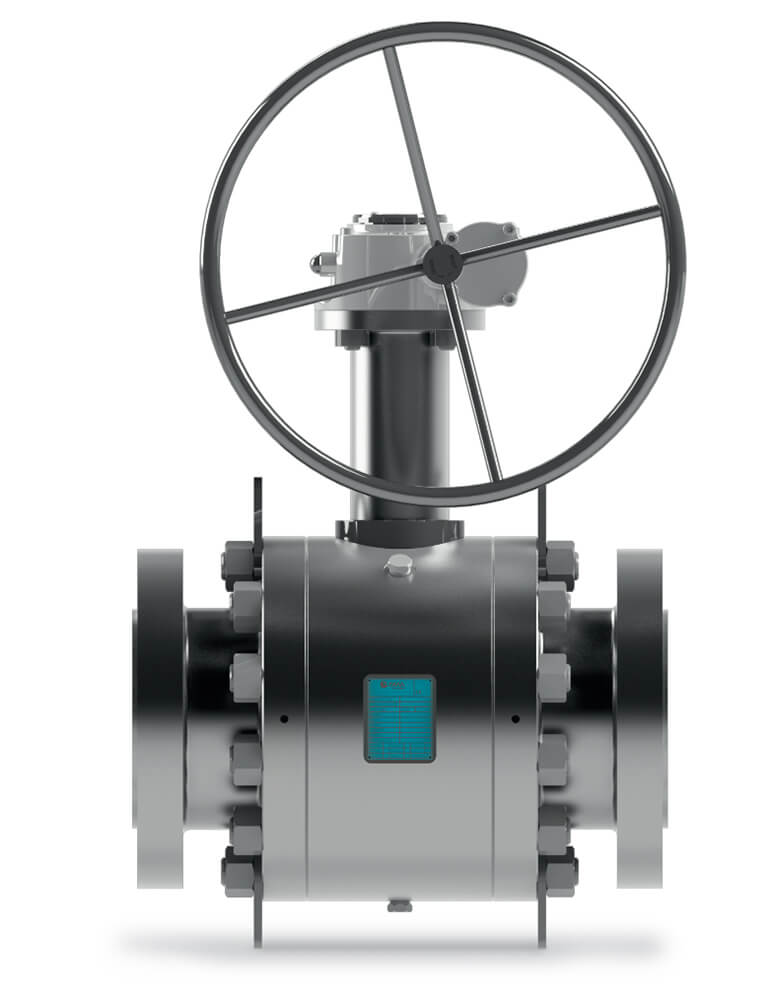
Stem extension can be supplied for high temperature or for easy manoeuvre.
CAM Ball valves are designed in accordance with API 607. In the event that the fire destroyed non-metal seats, the medium pressure pushes the upstream seat into the ball, and an appropriate shape of the seat cuts off the line fluid and prevents internal leakage. To prevent external fluid leakage a Fire safe Gasket is provided for all static and dynamic seal of the valve.
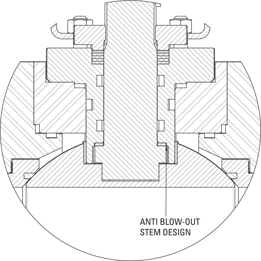
The design of the valve ensures that the stem cannot be blown out of the body, in the event of the gland being removed while the valve is under pressure.
This feature is provided according to API 6D.
Seat shape, stem washer/bearing and stem seal arrangements are designed to ensure minimal torque values.
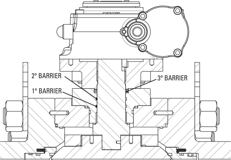
Our standard stem sealing are made of 2 sealing barriers with O-ring and a third barrier made with graphite. Different types of sealing could be made to meet customer?s requirements
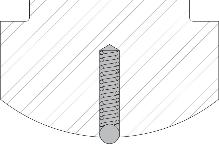
Internal parts that are insulated from the body may build up a static electric charge. When service conditions require electrical continuity to prevent static discharge, this is ensured by the adoption of coil springs between body, ball and stem.
Locking facilities can be provided to prevent accidental operation of the valve.
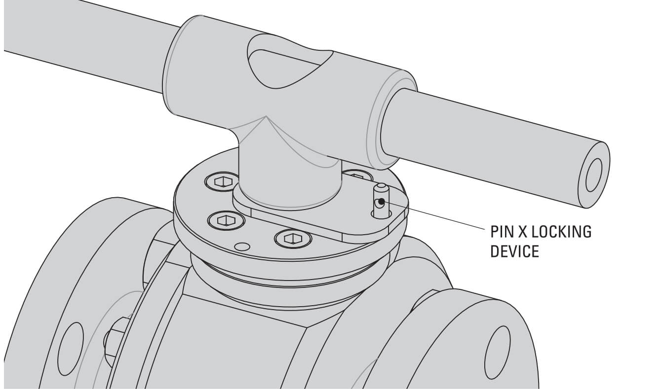
Locking facilities can be provided to prevent accidental operation of the valve.
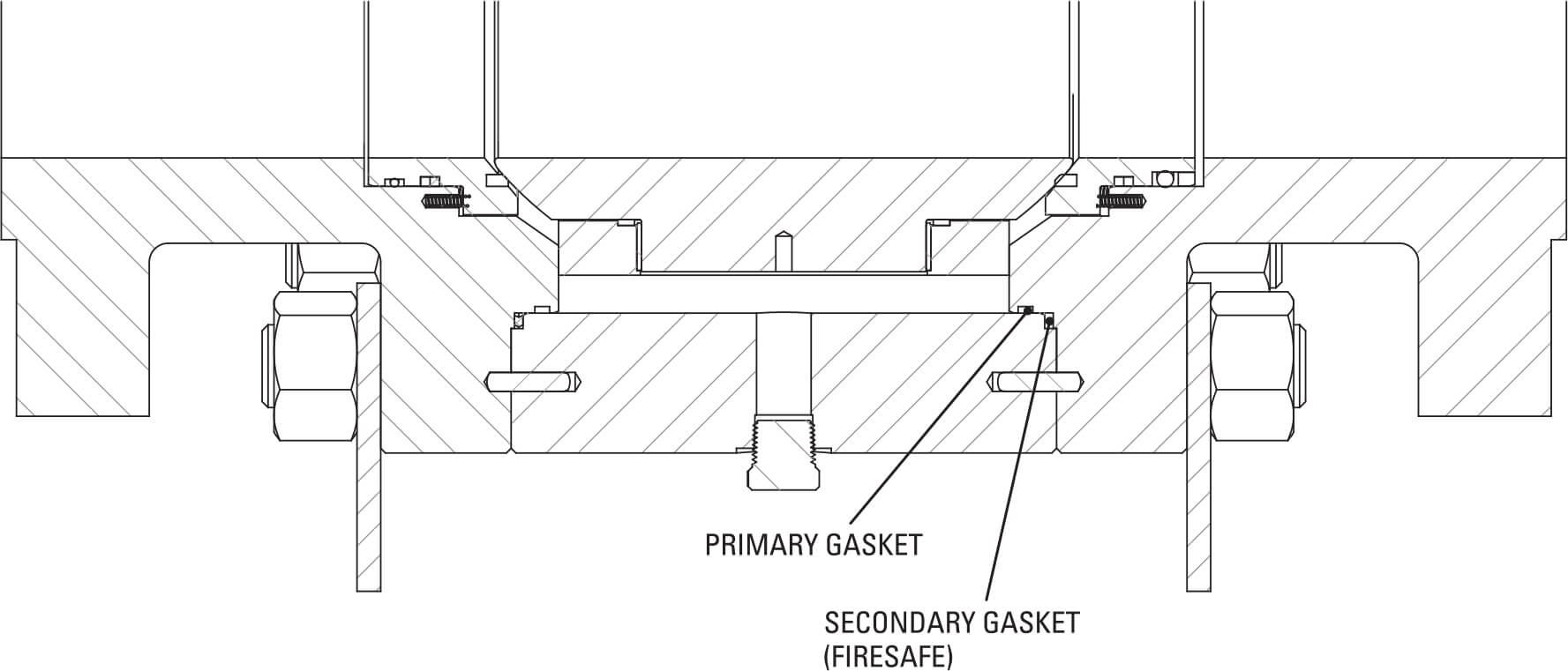
Primary and secondary gaskets (firesafe) may be provided in various materials and shapes; usually for CAM valves the first barrier is made in soft material (O-RING) and the second barrier in Graphite or Grahpite Spiral wound, according to the pressures and service conditions. Other types of sealing can be provided according to customer?s specifications.
A mechanical stop between stem and flange is provided to ensure control and precise alignment over ball rotation.
CAM valves provide lifting lugs for weight above 250 Kg and supporting feet for trunnion ball valves 6? and larger. This feature also could be supplied for all valves according to customer?s specification.
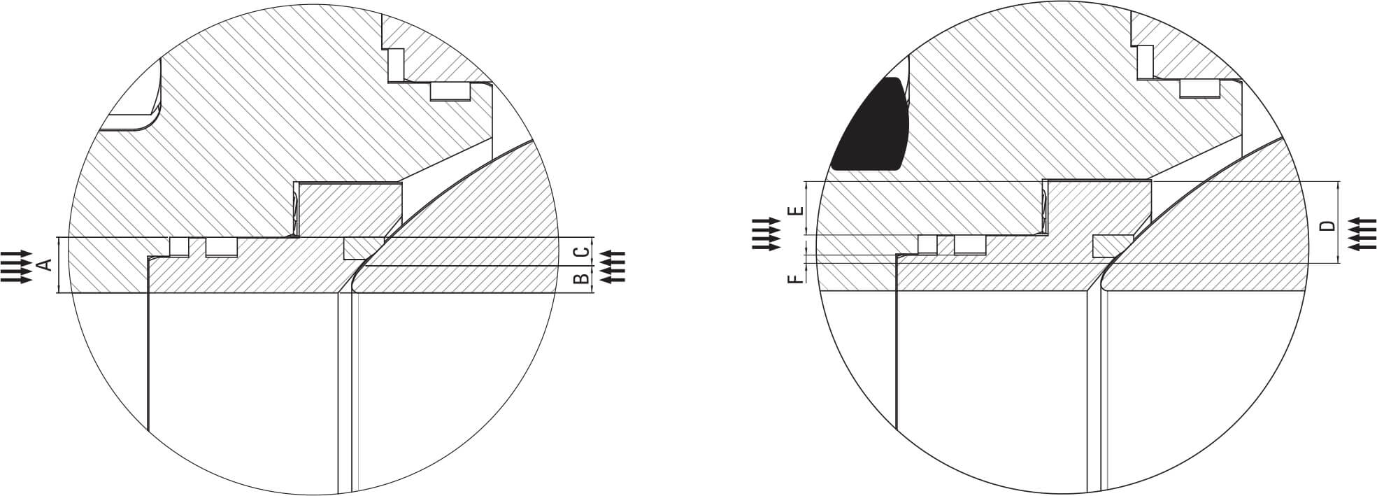
In the standard CAM Trunnion Ball valve, each seat ring performs a ?single piston effect?.
As line pressure increases, the seat differential area C = A – B creates a piston effect forcing the seat on the ball: the higher the line pressure, the tighter the piston action.
If pressure grows up into the cavity, it relieves to the line as the differential area F= D – E has greater force than the spring load.
On request the seat rings design can be modified to perform a ?double piston effect?.
In this case both seats or only one can be provided.
If both seats are DPE the pressure in the body cavity remains trapped and the valve can?t be self relieving (a pressure relief valve must be installed to protect the cavity from excess pressure).
Cam suggests to have one seat SPE and one seat DPE: in this case the valve remains self relieving and one double sealing barrier is guaranteed, The correct configuration for this option is: downstream side of the valve DPE and upstream SPE (self relieving).
Cam suggests to have one seat SPE and one seat DPE: in this case the valve remains self relieving and one double sealing barrier is guaranteed.
The correct configuration for this option is: downstream side of the valve DPE and upstream SPE (self relieving).
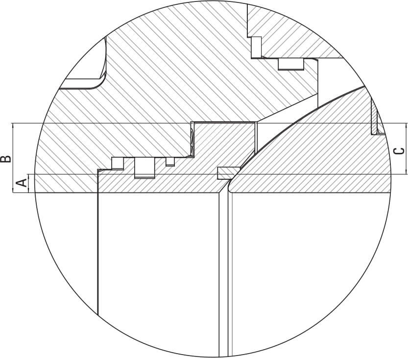
Seat seal may be designed to provide additional sealing capability: the cavity pressure enhances the contact pressure between seat and
ball, as the differential area A=B-C creates a piston effect forcing the seat on the ball.