Valves design
Valves material selection
Valves testing criteria and equipment
End User requirements
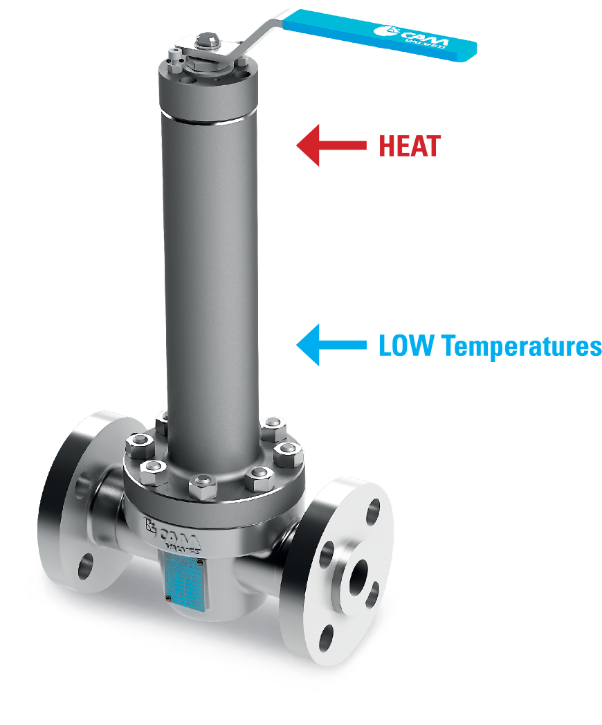
In cryogenic applications liquid gas is transmitted through the pipeline/valve at very low temperatures.
At these cryogenic temperatures the seals lose their resilient sealing properties becoming hard and brittle.
This is known as ?passing through the glass? phase.
The stem extension allows the ambient air temperature to heat up the liquid surrounding the stem, turning the liquid back to gas.
This gas becomes trapped in the stem extension and heats further to a point where the stem seals work more efficiently.
This volume of trapped gas is known as ?the vapor space?.
CAM valves are designed according to BS 6364 standard for non cold-box applications.
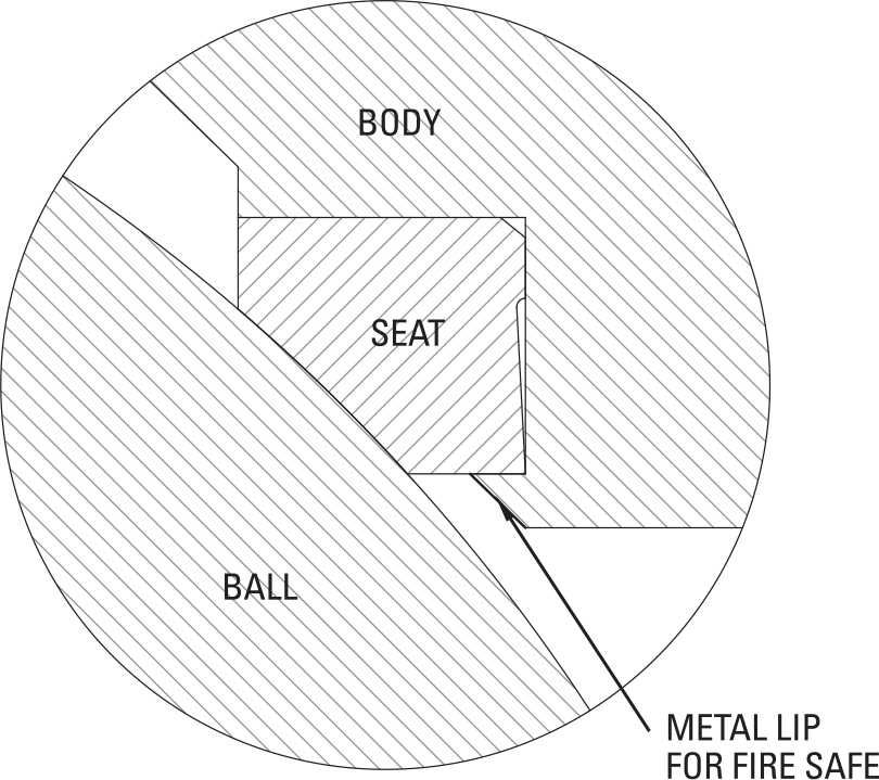
CAM cryogenic valves are designed and tested according to API 607. The valves are made with soft seat rings for primary seals, a secondary fire metal lip will come in contact with the ball in the event of fire and prevent leakage through the valve port.
For the static seal all valves are equipped with a secondary seal (?graphite? or ?metal?) to prevent external leakage in the event of fire.
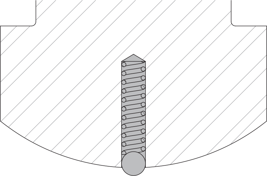
For hazardous and non-hazardous environments all CAM valves are equipped with an antistatic device that connects all parts of the valves to overcome the electrical charge of a non-grounded apparatus. This is achieved by permanent electrical continuity using a spring loaded stainless steel ball assembled in the valve stem, mantaining contact with stem/ball and stem and valve body.
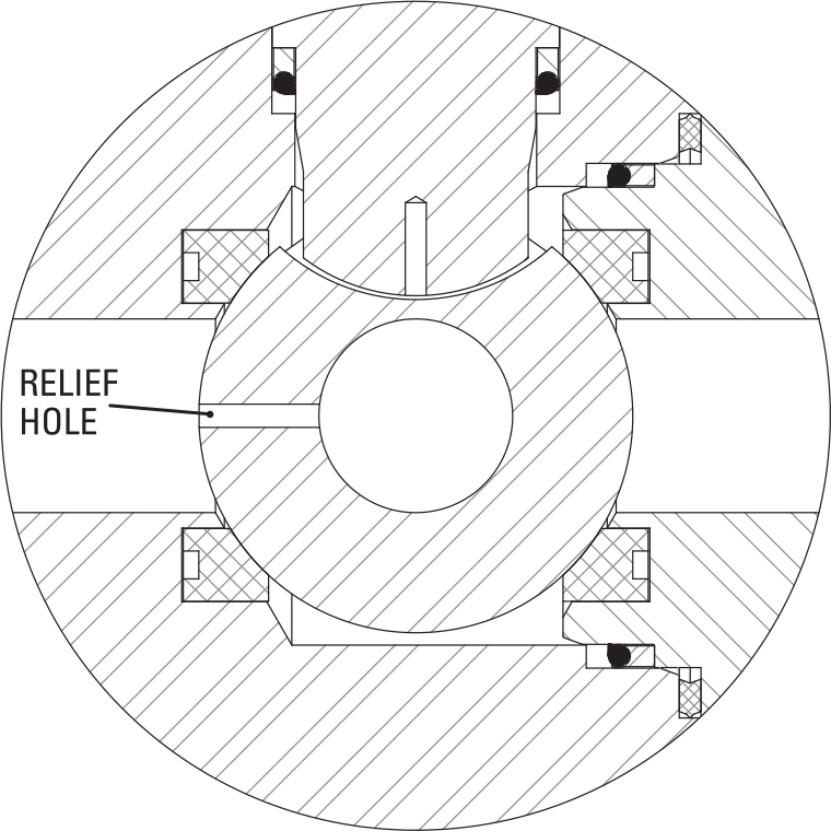
SELF-RELIEVING DESING
According to cryogenic standard (BS 6364) all CAM cryogenic valves are designed with a relief hole in the ball and with no trapped cavities to guarantee total elimination of the pressure that builds up due to thermal expansion.
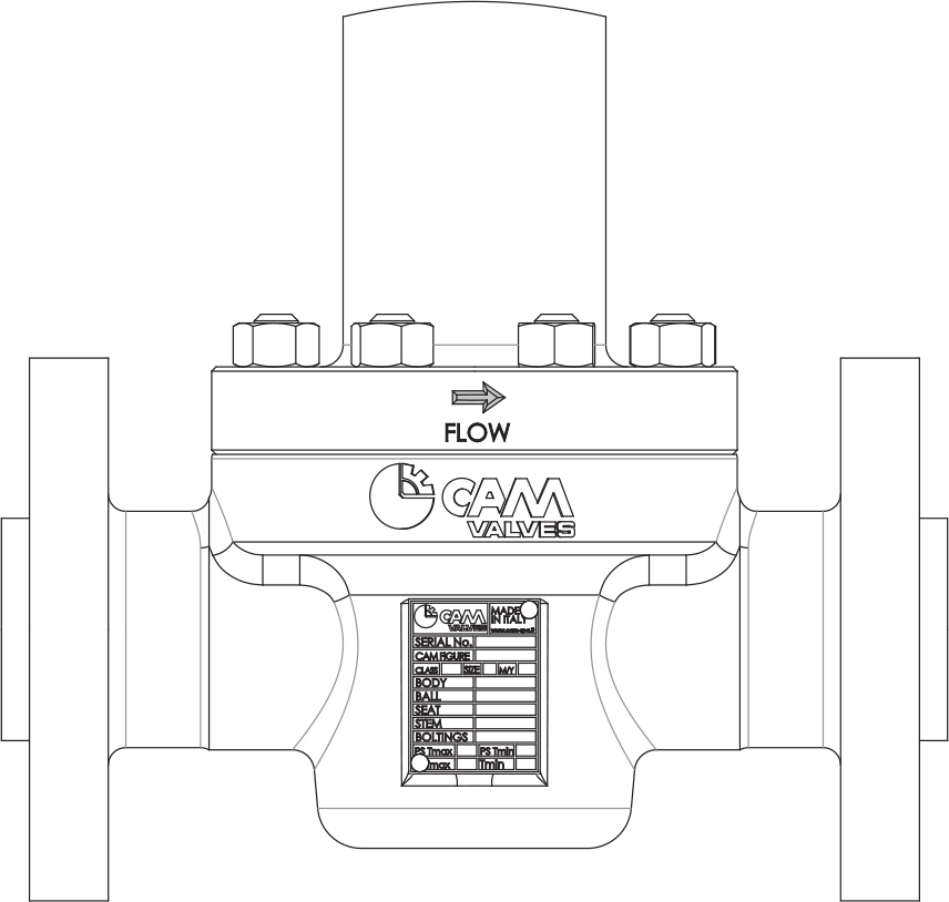
Valves are marked with an arrow to indicate the flow direction to ensure the correct installation on the plant.
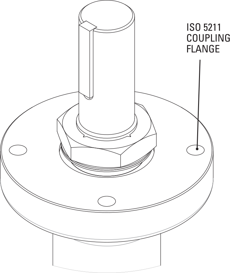
If an automation is required, all CAM valves are designed with a flange on the top in full compliance with ISO 5211.
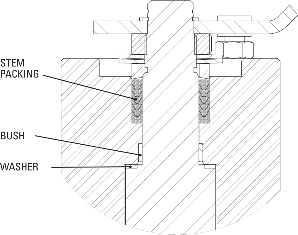
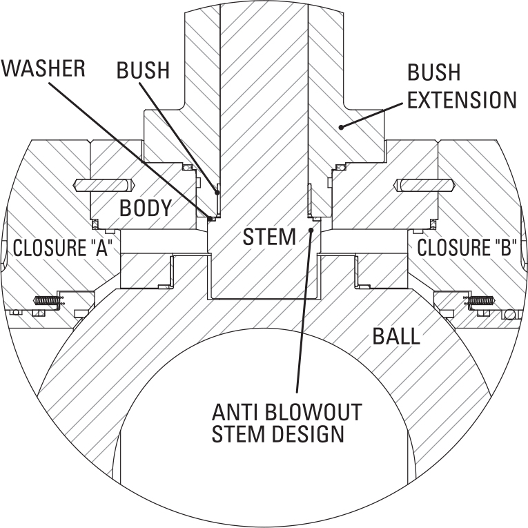
A special stem packing is installed on all CAM cryogenic ball valves.
This gasket is the consequence of a lot of internal testing and it guarantees a zero leakage during the life of the valve. The shape of the packing allows a dynamic sealing arrangement in case of stem load occurrence. To guarantee sealing due to erosion of the soft parts the packing is pre-loaded with two or more spring washers.
CAM cryogenic ball valves are designed with a one piece stem secured in the valve cavity with a large stem collar.
A washer is installed between the stem and the extension to reduce the operational torque.